Displacement of Gravity Dam in Far and Near Fault Earthquake Including Dam-Water-Sediment-Foundation Interaction
Farzad Bandei1 * , Gholamreza Azizian2 and Mohammad Hossein Golbarari3
1
Department of Civil Engineering,
University of Sistan and Baluchestan,
zahedan,
Iran
2
Department of Civil Engineering,
University of Sistan and Baluchestan,
Zahedan,
Iran
3
Department of Civil Engineering,
University of Sistan and Baluchestan,
zahedan,
Iran
Corresponding author Email: f_b_civil@yahoo.com
DOI: http://dx.doi.org/10.12944/CWE.10.Special-Issue1.115
Achieve adequate safety of dams against earthquakes is of particular importance, given that many dams have been constructed in seismic areas. In this study, the finite element method and ABAQUS software was used to o evaluate the performance of the SARIYAR dam in several earthquake with different nature of frequency. Dam-Water-Sediment-Foundation interaction was applied in the model to simulate the conditions affecting the response of the dam in a way that is consistent with the fact. Also ten different earthquake with near and far fault was selected to apply in the system. The impact of changes in the water level of the reservoir was also evaluated. The results indicated that the displacement was increased with rising in the water level. In Addition the far fault earthquakes had a significant influence on dam body responses in all cases.
Copy the following to cite this article:
Bandei F, Azizian G, Golbarari M. H. Displacement of Gravity Dam in Far and Near Fault Earthquake Including Dam-Water-Sediment-Foundation Interaction. Special Issue of Curr World Environ 2015;10(Special Issue May 2015). DOI:http://dx.doi.org/10.12944/CWE.10.Special-Issue1.115
Copy the following to cite this URL:
Bandei F, Azizian G, Golbarari M. H. Displacement of Gravity Dam in Far and Near Fault Earthquake Including Dam-Water-Sediment-Foundation Interaction. Special Issue of Curr World Environ 2015;10(Special Issue May 2015).
Available from: http://cwejournal.org?p=765/
Download article (pdf) Citation Manager Publish History
Select type of program for download
| Endnote EndNote format (Mac & Win) | |
| Reference Manager Ris format (Win only) | |
| Procite Ris format (Win only) | |
| Medlars Format | |
| RefWorks Format RefWorks format (Mac & Win) | |
| BibTex Format BibTex format (Mac & Win) |
Article Publishing History
| Received: | 2014-11-06 |
|---|---|
| Accepted: | 2014-11-06 |
Introduction
It is impossible to handheld computing of dam analysis due to existence numerous complexity in the interaction between related parts to dam. Hence the use of numerical tools such as finite element methods has become a standard principle in the dam engineering. Remarkable developments in software and hardware technology, allows to dam engineers to perform sophisticated numerical analysis with a high speed. Numerical simulation model of the dam-foundation system have been developed for different purposes. Determination of water-related structures such as dams and reservoirs, against hydrodynamic loads in structural design has a particular importance. The complexity of the models considered for the analysis of dams will be greater when considered several factors such as sediment in the model. Success in such studies requires an understanding of material behavior of dam, the dynamic load on the structure and selecting a good model for analysis. Westergaard studied the dynamic behavior of dam in the case of two-dimensional and under small periodic motions of the Earth. Kutsubo showed that the Westergaard solution was true just for vibrations with frequencies lower than the natural frequency of the reservoir.1 Chopra had generalized Westergaard solution. He showed that the hydrodynamic pressure response of horizontal ground motion is a function of different values in general. So that whenever earth frequency is less than the first natural frequency of reservoir, the imaginary part of the answer of dynamic response disappears and the Westergaard solution has correct answers.1 Asteris et.al discussed the nonlinear responses of the dam and reservoir system. They focused on the creation of an appropriate nonlinear model for concrete. After that analyzed different states may come to a concrete gravity dams under earthquakes in the nonlinear operation area of materials.2 Gao-Lin et.al was studied the Xialuodu dam constructed in china. They considered a 30% increase in allowable stress under earthquake excitation and 30% increase in the modulus of elasticity in dynamic mode and the damping ratio of 0.05 in modelling. Finally concluded that flexibility of the foundation causes a change in the frequency modes of dam-foundation motion.3 Zhang et.al analyzed three-dimensional shape of the valley in the massive and massless cases. In the case of massive, viscous boundary conditions were defined. Radiation waves caused by earthquakes in two orthogonal directions were excretion by the damper, at the end edge of the adsorbent and do not return to the dam system. The effect of gravity on the foundation was ignored to define a massless case. In this model, the foundation actually acts as a spring. For modeling of the fluid, the water is also considered to be incompressible. Thereafter the dam was modeled and analyzed in both linear and nonlinear behavior.4 Sherong Zhang and Gaohui Wang were analyzed near and far-fault earthquakes effects on the dynamic response of concrete gravity dam. They evaluated nonlinearity of materials and structural failure rate occurred in several cases.5
In this study, the main trend of the dam response was generated, with considering a general condition of the dam and studying it’s responses in all states. Scenarios have been considered for dam including several specific cases. These include effects of changes in the water level of the reservoir that happens for a dam in the different periods of construction, dewatering and exploitation. Also evaluation of the dam responses under near and far-fault earthquakes and impact of earthquake direction on the structural behavior.
Investigation of the Interactions
Dynamic Interaction of Dam-Water
In the two-dimensional finite element model, the interaction of water and structural equation is as follows6:

In which P, C11 and εν are related to pressure, bulk modulus and volumetric strain of fluid respectively. w is the rotation about the axis normal to the plane, Pw is the rotational stress andC22is the constraint parameter. In this study, the equations of motion of the fluid system are obtained using energy principles. Using the finite element approximation, the total strain energy of the fluid system may be written as6:

Where Uf and Kf are the nodal displacement vector and the stiffness matrix of the fluid system, respectively. An important behavior of fluid systems is the ability to displace without a change in volume. For reservoir and storage tanks, this movement is in the form of sloshing waves in which the displacement is in the vertical direction. Therefore, the effects of surface waves and sloshing behavior of the fluid must be taken into account. It is possible to describe the behavior of the free surface of the fluid in terms of the potential energy of the fluid. The potential energy of the systems due to the free surface motion can be written as6:

Where Usf and Sf are the vertical nodal displacement vector and stiffness matrix of the free surface of the fluid system, respectively. In addition, the kinetic energy of the system can be written as6:

Where Uf and Mf are the nodal velocity vector and the mass matrix of the fluid system, respectively. The equations of motion for a system can be derived directly from Lagrange’s equations. These equations are a direct result of Hamilton’s variations principle under the specific condition that the energy and work terms can be expressed in terms of the generalized coordinates and of their time derivatives and variations. If equations (2)–(4) are combined using the Lagrange’s equations, the following set of equations can be obtained6:

In which and are the system stiffness matrix including the free surface stiffness and the nodal acceleration vector, respectively. Rf is a time varying nodal force vector defined as -Mf ag when the earthquake ground acceleration is applied to the fluid system in which ag is ground acceleration vector.
Dynamic Interaction of Dam-Foundation
In this section dynamic equilibrium equations of dam-foundation interaction have been studied. Model is divided into three groups of nodal points including: 1) Joint nodes of dam and foundation showed with b; 2) Nodes of the dam that is shown by u; 3) Nodes of the foundation that is shown by f.
Equilibrium equations of the dam-foundation system in terms of displacement r to free field movement u is as equation,6 using the direct stiffness in structural Analysis:

In the above equation M, C and K are matrixes of mass, damping and stiffens,
respectively. uu is the motion dam rigid body, if free field movement of foundation ub be fixed.7 So:

Also dynamic equation of free field movement requires that7:

Therefore, by simplifying the right side of equation,6 this can be expressed as follow:

According to equation (9), it can be seen that right hand of this equation is without mass and viscous damping in foundation. Just need to conversion the time history functions to the frequency functions to transfer from the time domain to the frequency domain. Displacements have a harmonic behavior for harmonic excitation ..∪g(t) = ..∪g (ω)eiωt with ω frequency. Displacement vector can be expressed as r (t) = r(ω)eiωt7
Dynamic Interaction of Dam-Sediment
Substructure method was used to investigate this interaction. In this method interaction of dam-sediment has been divided into a series of simple sub interaction. Then the results combined to each other using the superposition principle of forces.8 In this way it is assumed that the interaction is happened just in the boundary of substructures. Equation of motion can be written as equation 108:

Force and displacement vector for applied harmonic excitation with ω frequency, can be written as follow8:

In which {Q} and {u} are force and displacement complex vectors in ω frequency. Eventually equation of motion is as follow for each frequency8:

Specifications of the Earthquakes
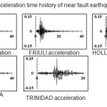
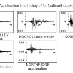
One of the most important parts of modeling the dynamic analysis, is select and apply an amplitude of earthquakes into the model. For this propose, ten earthquakes with different nature of frequency near and far fault were chosen and applied to the interface of dam-foundation interaction surface, in acceleration amplitude. The SEISMOSIGNAL software also used to scale the accelerations to 0.15g based on USBR regulation.9 It should be mentioned that according to this regulation earthquakes with fault distance over of 10 km from the ground level are known as far fault earthquakes and with less epicenter depth are considered in design as near fault earthquakes. Five earthquake including CHI-CHI, FRIULI, HOLLISTER, LOMA PRIETA and TRINIDAD are near fault earthquakes. The other five including IMPERIAL VALLEY, KOCAELI, KOBE, LANDERS and NORTHRIDGE, have epicenter more than 10 km and used as far fault earthquakes.10 All seismic acceleration spectrum used in this research is presented in appendix A and B.
Case Study
Model of a real constructed dam that the geometry and materials specifications used in the dam was available, had simulated. This is done for compliance with reality. To this purpose, SARIYAR concrete gravity dam was used as a case study. The dam is located in the Nallihan village, Ankara, Turkey and it was constructed in 1956 AD to produce hydroelectric power.6 Dam height from foundation is about 90 meters, width of crest at the top of dam is 7 meters and it rise 72 meters in bottom of dam body.6
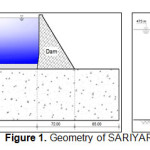 |
Figure 1: Geometry of SARIYAR dam Click here to View figure |
Finite Element Modelling
History of the finite element method is related to the early 19th century and practically in 90s was developed as a classical from and entered in engineering issues. This method has two features that distinguishes it from other existing methods,11 including: a) An integral formulation is used to create a system of algebraic equations; b) Smooth functions used to approximate the unknown parameters.11
The finite element method can be divided into five main stages: a) Dividing the area into several sub-areas called Elements; b) Determining an initial approximation to the solution as a function of the constants coefficients, which are either linear or second order; c) Extraction system of algebraic equations; d) Solving the system of generated equations; e) Calculating other quantities from the nodal values.11
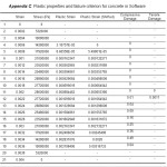
In this study, ABAQUS software was used to solve the finite element method equation and analyzing the dam-reservoir-sediment-foundation system. Model geometry was created similar to that shown in Figure 1. Also material properties is in accordance with Table 1.
![Table 1. Material properties [6]](http://www.cwejournal.org/wp-content/uploads/2015/05/Vol10_Spe_Disp_Farz_T1-150x150.jpg) |
|
Chu and Carrera equation was used to implement plastic failure behavior of concrete. For normal-strength concrete it is as follows12:

In which β represents the shape of stress-strain curve and is presented as follows12:

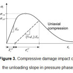
Two different failure mechanisms of concrete are tensile failure and compressive failure. Parameter ε∼Plt is tensile strain hardening and ε∼Ple is compressive strain hardening that showed in the Figures 2 and 3.21
![Figure 2. Tensile damage impact on tensile unloading behavior in unloading phase [13]](http://www.cwejournal.org/wp-content/uploads/2015/05/Vol10_Spe_Disp_Farz_fig2-150x150.jpg) |
|
May be due to inadequate characterization of materials, amount of ε∼Pleand in some cases be negative. In this case, error command will be issued by the software.13
 |
|

Returned hardening, is one of the most important parts of analysis during the hysteresis behavior of concrete. Compressive or tensile stiffness reversible factor can be determining in the software.13
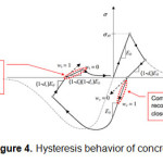 |
Figure 4: Hysteresis behavior of concrete Click here to View figure |
Laboratory data usually are consists of nominal strain and stresses and not true quantities. So, to implement these parameters into the software, they must be converted to their actual values.13

In which εnom and σnom are nominal strain and stress, respectively. Also ε and σ are their actual values. The difference between nominal and actual values increases with rising in strain and stress. Not Consideration of this fact can lead to significant errors in the results.13 Numbers related to graphs for plastic failure of concrete obtained from the above equations, are provided in Appendix C. All the studied accelerations spectrum were applied to the boundary surface of dam-foundation. In applying the boundary condition, it was considered a positive sign (to the downstream) and a negative sign (on the upstream), to evaluated the impact of the earthquake direction. In addition, three different modes for the reservoir were simulated including full, two-thirds and one-third of reservoir volume. Finally sixty obtained answers were compared to each other
 |
|
 |
|
 |
|
Results and Discussion
Convergence Analysis of Meshing
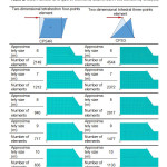
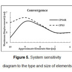
Mesh convergence analysis was conducted to obtain the optimal number of mesh used in the model. Sensitivity analysis is a useful ways to reducing the error of large mesh and avoid spending too much time for analyzing result by very small mesh. For this purpose, 5 different values ​​for the number of mesh are considered and. Also effect of the elements type on the obtain response was assessed. Approximate dimensions and number of elements in the two different types can be seen in the table 2.
 |
|
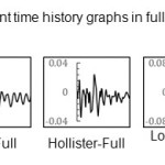 |
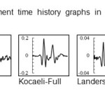
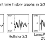
Appendix D: Displacement time history graphs in full reservoir under near fault earthquakes Click here to View Appendix |
In the above table, CPS4R element is a continuous plain stress four-point reduced integral element and CPS3 is a continuous plain stress three-point element. Under CHICHI earthquake loading with full reservoir and to the downstream, dam crest displacement time history graphs were obtained for each case of meshing. The maximum displacement extracted for each graphs and was considered as a comparison index for convergence.
 |
|
In CPS4R element with 10 meters approximately size (635 elements), the maximum displacement reached to 4.5 cm. By reducing the size of the elements to 7 m, the two lines collided to each other and reached to 5.5 cm. Then increase the number of element had not a significant effect on the structural response and still remained in the amount of 5.5 cm and the system was converged. The number of CPS3 elements in this size is 2372 and it is 1212 for CPS4R. So Selecting the CPS4R mesh type can have a significant impact in reducing the time of analysis in software. Therefore, in this study, the CPS4R element type with approximately size of 7 m was used.
 |
|
 |
|
Dam Seismic Responses
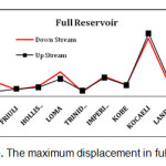
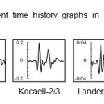
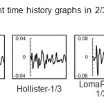
For naming the models, the name of earthquake at the beginning, then the water level and at the end direction of earthquake was coming. Displacement time history graphs of dam crest is presented in appendix D to I. As regards the vertical axis of the graphs represents the dam crest displacement in meters and horizontal axis shows the time in seconds. The behavior of structures during 40 Seconds of all earthquakes was presented. Absolute maximum displacement was extracted from the graphs and discussed.
 |
|
 |
|
 |
|
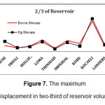
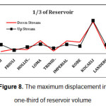
It is very clear that all graphs had a significant increase in KOCAELI earthquake. This earthquake has a high period compared to other earthquakes. The first integral of acceleration, generate velocity time history graph and it has large quantities for KOCAELI earthquake. Also to comply with it displacement caused by the earthquake are also large amounts compared to other earthquakes. Under CHICHI earthquake and in full reservoir state, dam seismic response to the downstream direction, is about 4 times higher than the upstream. However in most points, observed a little difference in performance of the structure in both earthquake direction. Therefore, in the design of structures faced the far fault earthquakes similar to KOCAELI, it should be considered the sudden pressure of the earthquake. Earthquake actions in both upstream and downstream directions, caused structural movement in the positive and negative direction of x diagram in the software, respectively. It is interesting that select the negative and positive directions for earthquake, had a negligible impact in dam crest displacement. Also, displacement of the dam was increased by rising the water level. Moreover, in all three cases considered for reservoir, the displacement spectrum was the same.
 |
|
 |
|
 |
|
Conclusion
Evaluating the behavior of SARIYAR dam under the various scenarios that may happen to it, specified that in dam site with high probability of far fault earthquake occurrence, analysis related to sudden loads such as blast and impact loads should be used. Also for structure that are built in near the fault evaluation of two first modes of the structure will suffice. Dams constructed in far distance of fault, the frequency and modal analysis and also exact determine of vibration characteristics of the dam is needed.
References
- Pasbani. KH. M., Gharrehbaghi. M., Abedi. K., (2012), “Dynamic analysis of concrete gravity dam including dam-reservoir-foundation interaction”, 2nd National conference on dam construction, Azad university of Zanjan, Iran.
- Asteris, P.G., Tzamtzis, A.D., (2003), “Nonlinear Seismic Response Analysis of Realistic Gravity Dam Reservoir Systems”, International Journal of Nonlinear Sciences and Numerical Simulation, Vol. 4, pp. 329-338.
- Gaolin, Zhi-qiang, H., Shi-Yun, x., Jian, B.L., (2004), “Some problems on the seismic design of lerge concrete dams”, Thirteenth world conference on earthquake engineering., ELSEVIER.
- Heirany, Z., Ghaemian, M., (2012), “The effects of foundations modulus of elasticity on concrete gravity dams behavior”, Indian journal of science and technology, Vol. 5, p.p. 32-46.
- Zhang, S., Wang, G., (2012), “Effects of Near-Fault and Far-Fault Ground motions on Nonlinear Dynamic Response and Seismic Damage of Concrete Gravity Dams”, Soil Dynamic and Earthquake Engineering., Vol. 53., ELSEVIER.
- Akkose, M., Simesk, E., (2012), “Non-linear Seismic Response of Concrete Gravity Dams to Near-Fault Ground motions including Dam-Water-Sediment-Foundation interaction”, Applied Mathematical Modelling, Vol. 34., ELSEVIER.
- Moghddam. H., (2003), “Earthquake Engineering (Principles and Applications)”, Farhang publication, Iran.
- Hariri, M., Mirzabozorg, H., (2012), “Effects of near fault ground motions in seismic performance evaluation of a symmetric arch dam”, soil mechanics and foundation engineering, Vol. 49, No. 5, Russian.
- USBR, (1976), “Design of Gravity Dams”, United States Department of the Interior, USA.
- Wesnousky, S. G., (1986), “Earthquakes, quaternary faults, and seismic hazard in California” Journal of Geophysical Research (American Geophysical Union), Vol. 11.
- Mehmet, A., Erman, S., (2010), “Non-linear seismic response of concrete gravity dams to near-fault ground motions including dam-water-sediment-foundation interaction”, Applied Mathematical Modelling, Vol. 34, Issue 11, p.p. 3685-3700.
- Darly, L. A., (2007), “First Course in the Finite Element Method”, University of Wisconsin–Platteville.
- Daun, C., Catri. K.H, (1985), “Stress-Strain Relationship for Plain Concrete in Compression”, ACI Journal.
- Abaqus/Explicit: Advanced Topics, Material in Abaqus, Lecture 3.
- Gaolin., Ruifang, Z., Fuming, W., (1988), “Structure-foundation interaction effects on seismic loads reduction of concrete gravity dams”, Ninth World conference on earthquake engineering, Vol. 8, Japan.
- Hariri, M., Mirzabozorg, H., (2011), “Reservoir fluction effects on seismic response of high concrete arch dam considering material nonlinearity”, journal of civil engineering.
- Tahar, B.A., Belharizi, M., Bekkoche, A., (2011), “Modal behavcior of dam-reservoir-foundation system”, EJGE, Vol. 16.
- Hong, Z., Gao, L., (2009), “Numerical simulation of damage in high arch dam due to earthquake”, Higher Education Press and Springer, China.
- Bouaanani. N., Reanud. S., (2014), "Effects of fluid–structure interaction modeling assumptions on seismic floor acceleration demands within gravity dams", Elsevier, Engineering Structures, Vol. 67, p.p. 1-18.
- Heirany, Z., Ghaemian, M., (2013), “Effects of foundation in dynamic analisys of concrete gravity dams”, Journal of the croatian association of civil engineers, croatian.
- FERC. (2002). “Manual for engineering guidelines for the evaluation of hydropower projects”.
- Xu. Q., Chen. J., Li. J., (2012), "A Study on the Functional Reliability of Gravity Dam", Scientific Research, Energy and Power Engineering, Vol. 4, p.p. 59-66.
- Valamanesh. V., Estekanchi. H. E., Vafaei. A., Ghaemian. M., (2011), "Application of the endurance time method in seismic analysis of concrete gravity dams", SCIENTIA IRANICA, Sharif University of Technology, Vol. 18, p.p. 326-337.
- Paggi, M., Ferro. G., Braga. F., (2013), "A multi scale approach for the seismic analysis of concrete gravity dams", Elsevier, Computers and Structures, Vol. 122, p.p. 230-238.
- Zhang Sh., Wang. G., Yu. X., (2013), "Seismic cracking analysis of concrete gravity dams with initial cracks using the extended finite element method", Elsevier, Engineering Structures, Vol. 56, p.p. 528-543.
- Sun. G. H., Zheng. H., Liu. D. F., (2011), "A three-dimensional procedure for evaluating the stability of gravity dams against deep slide in the foundation", ELSEVIER, International Journal of Rock Mechanics & Mining Sciences, Vol. 48, p.p. 421-426.
- Escuder-Bueno. I., Altarrejos-Garcia. L., Serrano-Lombillo. A., (2012), “Methodology for estimating the probability of failure by sliding in concrete gravity dams in the context of risk analysis”, ELSEVIER, Structural Safety, Vol. 36-37, p.p. 1-13.
- Leger. P., Bretas. M. E., Lemos. J. V., (2012), “3D Stability analysis of gravity dams on sloped rock foundations using the limit equilibrium method”, ELSEVIER, Computers and Geotechnics, Vol. 44, p.p. 147-156.
- Kartal. M. E., Bayraktar. A., Basaga. B. H., (2010), "Seismic failure probability of concrete slab on CFR dams with welded and friction contacts by response surface method", ELSEVIER, Soil Dynamics and Earthquake Engineering, Vol. 30, p.p. 1383-1399.


